Posted by Robert M. Haney, PE on Aug 1st 2022
Arc Suppression of Solenoid Coils
The inductance of the solenoid valve coil causes a voltage transient when the coil is suddenly switched off, often resulting in the need for arc suppression devices to be placed across the coil. If the voltage is disconnected by a switch contact or a relay contact, an arc is generated across the contact that can reach several hundred volts. This arcing can result in degradation and eventual failure of the contact. If a solid-state switch (Transistor or MOSFET) is used this voltage transient can result in over-voltage failure of the solid-state switch if it’s not protected.
Inductance is typically not specified on valve or coil drawings or on data sheets. It is generally not a controlled characteristic for the coil design. The coil voltage/current ratings and resistance are specified on drawings and data sheets. The inductance can be measured, though.
The terms resistance and impedance are often used interchangeably but technically they are not the same. The customer might sometimes ask for impedance when he/she really means the resistance. For a complete discussion of the coil parameters of resistance, inductance, impedance, and reactance refer to the article on coil parameters. For a DC voltage applied to an ON/OFF valve the inductance does not affect the steady state current flow. It merely provides a short delay in current response. (An exponential response with a Time Constant of Ƭ = L/R mSec) where L is in mH, R is in Ohms.
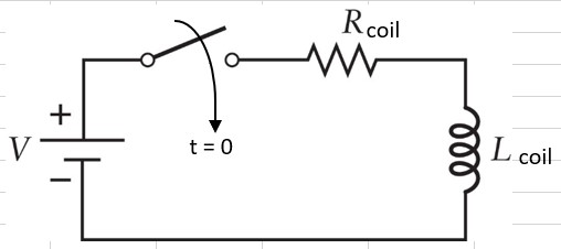
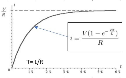
Figure 1: Exponential Current Response for a Step Voltage Applied to a Solenoid Coil
The Time Constant for coils is typically less than a few milliseconds for the bare coil, but increases to a much longer time when mounted on the valves. The coil inductance results in an inductive voltage transient when the coil current is turned off. This voltage transient will result in arcing that can be damaging to the electronic switches or the electromechanical switches or contacts that drive the coil. The devices that drive the coil are typically protected from this damage by placing a diode, MOV, or TVS suppressor across the coil. The suppressor can be embedded in the coil or installed externally in the electrical circuit or the electronic control system.
The scope plot below shows the typical DC coil voltage and current waveforms with no coil suppression device. The voltage scale is 100V/cm. The current scaling is 0.4A/cm. Note the pull-in waveforms are as expected; an exponential rise in current for a step input voltage of 24VDC. The brief reduction in current at pull-in is due to the voltage generated by the velocity of the solenoid actuator when it pulls in. Note the dropout waveforms show the abrupt drop in current and a large voltage transient of nearly -300VDC. The voltage transient can be even higher than that depending on the inductance and dielectric breakdown voltage of the air across the switch contact. This voltage will cause damage or degradation to the valve control switch (arcing in an electromechanical contact or excessive voltage on solid state devices).
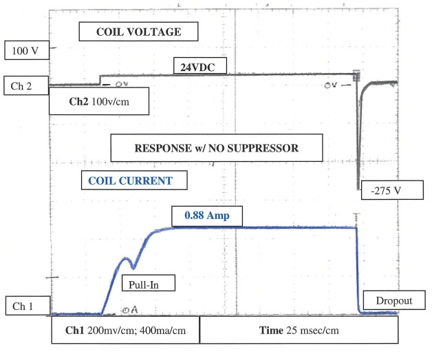
Figure 2: Typical DC Coil Voltage and Current Waveforms with No Coil Suppression Device
One method for voltage transient suppression is to just put a resistance in parallel with the inductance (across the solenoid coil). Figure 3 below shows a solenoid coil having a resistance of 10 ohms and an inductance of 100 mH. It’s powered by a 12-volt source through a switch, and it is shunted by a parallel suppression resistor.
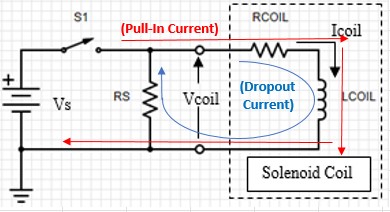
Figure 3: Resistor Coil Suppression Circuit
When the switch is closed the current through the coil builds exponentially to 1.2 amps. Later the switch is opened, and a negative voltage transient is generated at Vcoil by the inductance of the coil to resist the sudden change in current through the coil. The coil current and voltage responses resulting for a suppression resistance of 50 ohms are displayed on the left side of figure 4. The current builds to 1.2 amps in about 40 msec. When the switch opens at ~100 msec, the current decays to zero in about 25 msec and the voltage spikes to about -60V. If the suppression resistance were removed the voltage spike would rise to hundreds of volts (see the right side of figure 4) and arcing would occur across the switch contact.
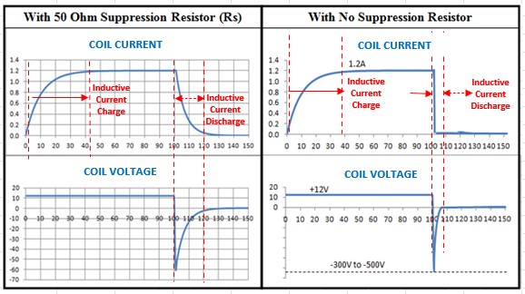
Figure 4: Coil Current/Voltage Response With and Without 50-ohm Rs
The power dissipation in the coil and the suppression resistor are shown in figure 5. The coil dissipation is about 14 watts but there is an additional 2.9 watts dissipation in the suppression resistor while the coil is energized. When the switch is opened and the coil is de-energized there is a pulse of power dissipation (peak power 72 watts) lasting about 10 msec in the suppression resistor. The suppression resistor would require a power rating of about 5 watts or more depending on the rate at which the coil is cycled on and off and the ambient temperature of the resistor.
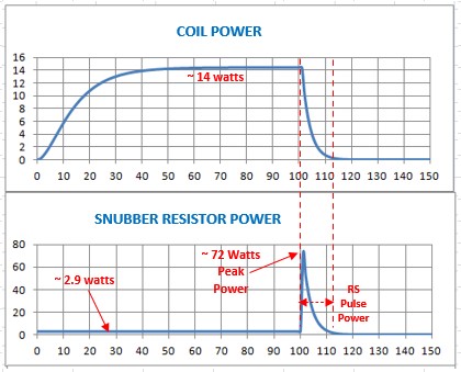
Figure 5: Coil & suppression resistor power dissipation.
The 50-ohm, 5-watt suppression resistor limits the voltage spike to ~60 volts. The advantage of this suppression method is that it is simple. The disadvantage is the cost of the 5-watt resistor and the wasted 2.9 watts of power. To reduce the wasted power in the suppression resistor it could be increased to 100 ohms. The wasted power would be cut in half, but the negative voltage would double.
Another circuit commonly used for transient suppression is the resistor-capacitor snubber circuit in which a capacitor is placed in series with the suppression resistor as shown in figure 6 below. When the switch is closed the current through the coil builds to a current of 1.2 amps. In addition the capacitor Cs is charged to 12V through the resistor Rs. Later the switch is opened and a negative voltage transient is generated at Vcoil by the inductance of the coil to resist the sudden change in current through the coil.
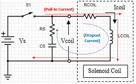
Figure 6: Resistor-Capacitor Coil Suppression Circuit
The coil current and voltage responses resulting for a suppression resistance of 50 ohms and a suppression capacitance of 0.1 uF is similar to that for the resistor shown in figure 3. The coil current response is similar, but the voltage transient is lower and more gradual due to the added capacitor. The current builds to 1.2 amps in about 40 msec. When the switch opens, the current decays to zero and the voltage spikes to about -60V.
The coil power dissipation is the same as for the resistor suppression (~14 watts) but there is no additional 2.9 watts dissipation in the suppression resistor (Rs) while the coil is energized. When the switch opens and the coil is de-energized there is a pulse of power dissipation in the suppression resistor. The suppression resistor requires a much lower power rating (one-quarter to one-half watt) depending on the rate at which the coil is cycled on and off and the ambient temperature of the resistor. The values and ratings of capacitance and resistance needed, can be approximated from the following formulas developed by C.C. Bates:
Cs(uF) = (Icoil)2 / 10
Rs = Vs / [10 x (Icoil) x (1+ (50/Vs))]
The induced voltage at contact opening is: V = (Icoil) x Rs = (Rs / Rcoil) x Vs
The R-C suppressor is effective in both AC and DC circuits. Typical suppressors are a 47 ohm, ½ watt resistor and a 0.1 uf, 250V capacitor. The capacitor should be non-polarized. The R-C network can be obtained as a single devise in an encapsulated package.
The most commonly used suppression method is the diode suppressor. It avoids the cost and power dissipation of the RC network and has a very low voltage transient when the coil is turned off. The scope plot in figure 7 below shows the coil voltage and current waveforms with a diode suppressor connected across the DC coil (Cathode to positive, Anode to negative). The voltage scale is 20V/cm. The current scaling is 0.4A/cm. Note the pull-in waveforms are as expected (the same as above). Note the dropout waveforms show no large voltage transient (clamped at about -0.75 V by the diode), and a slow exponential drop in current.
This diode suppression method solves the large voltage transient but has a slower dropout time (~ 33 msec in this case). This limits the maximum rate at which the coil may be cycled on and off (~ 11 cycles per sec). The valve response time is typically slower than this, so this is generally not a concern for most solenoid actuator or valve applications.
Another disadvantage of the diode suppressor is the importance of observing proper polarity of the diode. The Cathode must be connected to the positive coil terminal and the Anode must be connected to the negative coil terminal. Reversing the polarity will result in excessive current though the diode when the solenoid is energized.
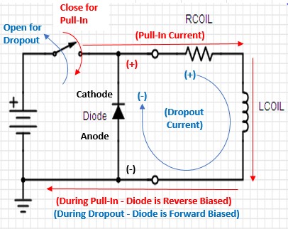
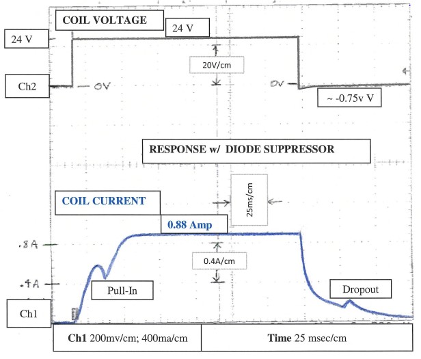
Figure 7: Typical DC Coil Voltage and Current Waveforms with Diode Suppression
Another common suppression method for DC coils is the bi-directional TVS (like the P6KE33CA). A TVS can be unidirectional or bi-directional. Proper polarity must be observed for the unidirectional device. Polarity does not matter for the bi-directional TVS. The scope plot in figure 8 below shows the coil voltage and current waveforms with a P6KE33CA bidirectional TVS suppressor. The voltage scale is 20V/cm. The current scaling is 0.4A/cm. Note the pull-in waveforms are still as expected; an exponential rise in current for a step input voltage of 24VDC. Note the dropout waveforms show a voltage transient of -33V, and a faster drop in current than when a diode is used.
The TVS suppression method has the advantage of a quicker dropout time (~ 5 to 10 msec in this case). The maximum rate at which the coil may be cycled on and off would be about 22 cycles/sec (the valve response time is typically much slower than this). A bi-directional TVS might be slightly more expensive than a diode, but it has the advantages of faster turn-off and no concern for polarity.
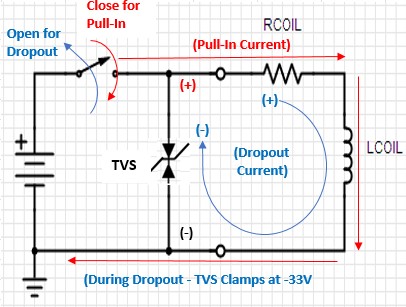
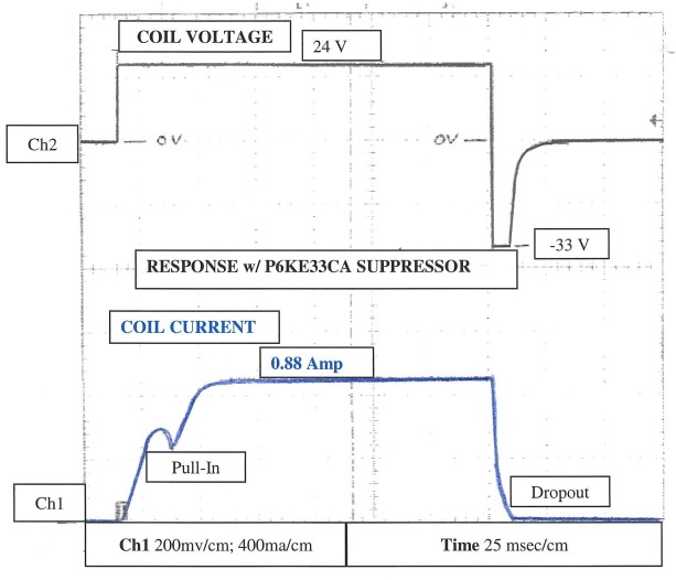
Figure 8: Typical DC Coil Voltage and Current Waveforms with TVS Suppression
The common suppression device used on AC coils is the metal oxide varistor or MOV. It is a bidirectional clamp device like the TVS device above, but is based on MOS technology rather than bipolar PN junction technology. Suppressors used on AC coils must be bidirectional, because with AC, the voltage changes polarity 120 times per second. For a 24Vrms voltage, the peaks of the voltage waveform are +/- 34v (24Vrms x 1.414 = 34vpeak). So, the clamping voltage for the MOV must be greater than 34V (typically 40V minimum). For a 115Vrms voltage, the peaks of the voltage waveform are +/- 162v (115Vrms x 1.414 = 162vpeak). So, the clamping voltage for the MOV or must be greater than 162V (typically 175V minimum).
Some AC coils have an integral bridge rectifier that converts the applied AC voltage into full-wave rectified DC voltage (See Figure 5 and 6 below). The coil current is DC with a 120Hz AC ripple current. So it is actually a DC coil. This type of AC coil provides suppression through two series diodes that are connected across the coil (providing clamping at about 1.5v DC).
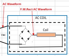
Figure 9: AC Coil with Integral Bridge Rectifier
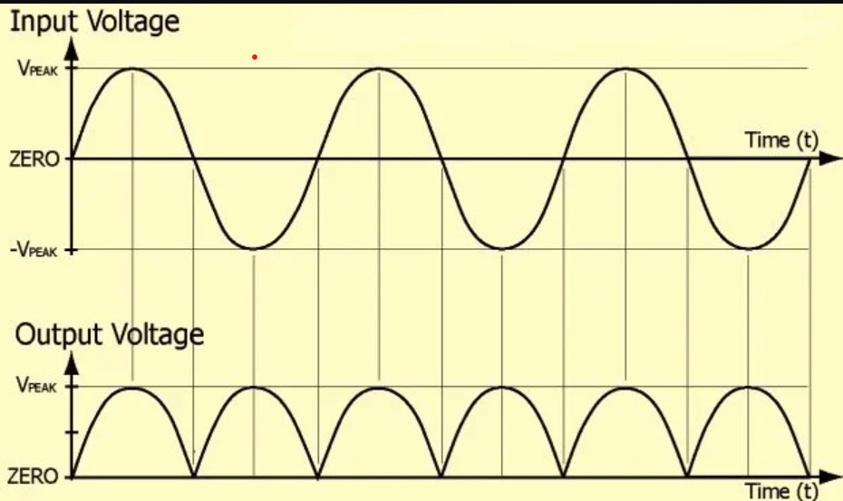
Figure 10: Bridge Input & Output Voltage Waveforms
In addition to making the decision about which suppression device to use, the system designer must also decide on where to locate the device. Should it be placed at the voltage source driving the coil? Or should it be placed in the coil itself? The common theory is that it’s best to place it close to the coil – the source of the transient voltage. However, placing the suppressor in the coil adds to the cost of manufacturing the coil. Electronic controls used to drive solenoid coils typically have built in protection for the inductive transient caused by coil inductance. This eliminates the need for a suppression device to be embedded into the coil.
There may sometimes be concern over EMI issues that can arise within the machine cables. Sensitive signals from sensors or transducers in the machine may be disturbed by the electric/magnetic fields generated by the rapid transitions in voltage and current when solenoid coils are operated. Placing the suppression device close to the coil would keep the current transient in the coil. The voltage transient would still be present in the cable. This can be further minimized by shielding and separating sensor cables from solenoid cables.
About the Author - Robert M. Haney, PE
Robert M. Haney, P.E. (Rockford, Illinois), is an electrical engineering consultant and adjunct instructor with nearly 40 years of experience in the design, application, and field support of electronic controls and test equipment. He has written extensively about his areas of expertise, including "Solenoid Control, Testing, and Servicing" published by McGraw Hill (Available on Amazon.com). Robert is a registered Professional Engineer in Illinois with a BSEE from General Motors Institute (now Kettering University) and an MSEE from Marquette University. In addition to experience with controls for industrial engines, off-highway equipment, electric power generators, machine tools, and automatic machinery, he has taught DC/AC circuits, electronics, and technical math for Rock Valley College and mathematics for Rasmussen College, Embry-Riddle Aeronautical University, and Upper Iowa University. Mr. Haney has held engineering positions with United Technologies, Caterpillar, Delco Electronics, and Barber Colman Company, and consulting positions with Delta Power Company, Collins Aerospace, M'TE Hydraulics, and Dynacorp. He holds a patent on a tractor draft control system assigned to J.I. Case that uses solenoid coils as sensors (U.S. Patent #4,064,945). He is an active member of IEEE (Institute of Electrical and Electronics Engineers) and the Chicago/Rockford IEEE Consultants' Network; much of his work has been with the electronic control and testing of solenoids and solenoid-based devices.

