Posted by Robert M. Haney, PE on Apr 21st 2022
Solenoid Coil Resistance vs Temperature
The thermal environment is very important for a solenoid coil that provides the force generated for the solenoid actuator or valve. One such issue that can arise is if the solenoid valve is to be used in a hot ambient temperature and the coil is in continuous duty, the coil temperature may exceed the rating of the magnet wire or the resistance may be too high to provide the current required for proper operation at the available voltage. Understanding the relationship between coil resistance and temperature can ensure that your system continues to run optimally.
The actuator force is a function of the Ampere-Turns (NI) provided by the solenoid coil. The force generated in a solenoid actuator or solenoid valve is determined by the current applied to the solenoid coil. And the current is a function of the applied voltage and the resistance or the impedance of the coil.
The resistance of a DC coil is simply the ratio of the applied DC voltage to the DC current at room temperature (~20DegC or 25DegC). The impedance of an AC coil is simply the ratio of the applied AC voltage to the AC current at room temperature. The resistance will increase with increased coil temperature due to the temperature coefficient of resistance of the Copper wire.
The temperature of the coil is a complex function of many factors including:
- The self-heating due to the coil power dissipation (I2R)
- The ambient temperature
- The thermal resistance between the coil and its surroundings (convection to ambient, conduction to the manifold, radiation to/from surrounding surfaces, etc.)
The Resistance of solenoid coils can be measured directly with a DMM. Resistance of AC coils that have an integral bridge rectifier cannot be measured directly with a DMM. To measure the resistance of this type of solenoid coil, refer to the article on “Solenoid Coil Parameters – Their Effects and Measurement (Resistance, Inductance, Reactance, Impedance, & Turns Count)”.
The increase in electrical resistance of the coil with temperature is due to the Temperature Coefficient of Resistance of Copper (Alpha in the formula given below):
R(T) = R@25C [1 + Alpha (T - 25)]
Where:
Alpha = 0.0039
R(T) = Wire Resistance (ohms) @T
R@25C = Wire Resistance (Ohms) @ 25C
T = Wire Temp (in Deg C)
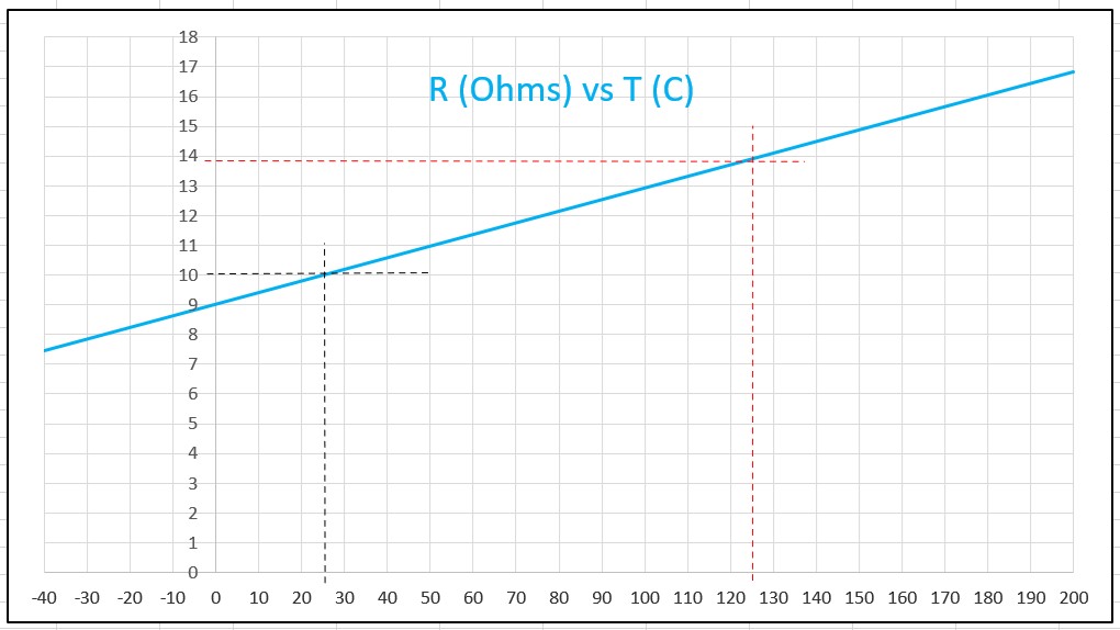
For a solenoid coil with a resistance of 10 Ohms at 25 DegC, the resistance will increase to 13.9 Ohms at a wire temperature of 125 DegC. So for a 100 DegC increase in wire temperature there’s a 39% increase in resistance. The graph below shows the relationship of resistance vs temperature for this coil over the range of -40 DegC to 200 DegC.

Solenoid Coil Resistance vs Temperature
The increase in resistance for the 10 ohm coil when its temperature is increased from 25 DegC to 125 DegC is calculated below:
R(125) = 10 [1 + 0.0039 (125 - 25)]
R(125) = 10 [1 + 0.0039 (100)]
R(125) = 10 [1.39] = 13.9 Ohms
This shows how important the thermal environment is for a solenoid coil that provides the force generated for the solenoid actuator or valve. The actuator force is a function of the Ampere-Turns (NI) provided by the solenoid coil. If the coil gets too hot the ampere-turns can degrade to a level that limits the solenoid valve performance. The force generated by the current may not be sufficient at the available voltage.
The coil temperature is a function of the power (Watts or I2R) dissipated in the coil, the ambient temperature, and the thermal resistance between the coil and the ambient air. The thermal resistance includes the thermal conduction through the coil encapsulant, the solenoid valve & manifold, and other factors of the environment around the coil (heat transfer via convection, and radiation).
It is difficult to accurately model all of the factors detailed above to determine the maximum temperature of the coil. An additional factor to consider is the electrical duty cycle of the coil in the valve application. Is it ‘Continuous Duty’ (on 100% of the time) or ‘Intermittent Duty’ (cycling ‘ON and OFF’ at some lower ‘Duty Cycle’)? For example, if the valve application were ~1 Second ON and ~9 Seconds OFF, the thermal duty cycle for the coil is only ~10% resulting in one-tenth the average power dissipation.
A good practice is to run some tests on the coil in the actual valve application. The coil resistance can be checked after one-half to one hour of operation. This resistance can be compared to the room temperature resistance of the coil. Solving the equation above for T gives:
T = [(R(T)/R25C) -1]/0.0039 +25
For example, if the 10 Ohm coil above increases to 16 Ohms after one-half to one hour of operation:
R(T) = 16, R25C = 10
T = [16/10 – 1]/0.0039 + 25
T = 0.6/0.0039 + 25
T = 153.8 + 25 = 178.8 DegC
If the temperature rating of the copper magnet wire is ~200 DegC this may be an acceptable temperature for this coil. If the wire temperature were to approach 200 DegC this would not be acceptable. If it’s decided that the wire temperature needs to be reduced, several strategies can be considered. The thermal resistance might be reduced by providing better heat transfer for the coil through improved air flow, insulating the coil from other nearby heat sources, or reducing the power dissipation by a different choice of coil.
Of course, in addition to the coil temperature being limited to a safe level for the Copper magnet wire rating, the coil resistance at that temperature must result in a coil current that is high enough to operate the solenoid actuator or valve. If the Ampere-Turns (NI) of the coil is too low the force available to operate the valve actuator or valve might be too low.
For AC coils, the AC impedance is the combination of the coil resistance and the inductive reactance. And the inductive reactance is typically larger than the resistance. So the temperature effects are somewhat lower for AC coils.
Another strategy that could be employed for DC On/Off actuators or valves is to reduce the temperature and resistance of the coil by using electronic ‘Peak & Hold’ control.
Since the ‘Holding Current’ for the actuator or valve is typically much less than the ‘Pull-In Current’ the controller could apply ‘PWM Current Control’ that applies full current for ‘Pull-In’ and then (after a short delay) reduces the ‘PWM Duty Cycle’ to 50% or less to a level that is still above the ‘Hold-In Current’. This would significantly reduce the coil power dissipation, the wire temperature, and the coil resistance. For further details on this PWM control approach a future article will be written on “PWM Control for ON/OFF Solenoid Valves”.
For both On/Off and proportional solenoid actuators or valves, the application engineer needs to ensure that the current that’s available at the highest coil temperature (maximum resistance) and minimum supply voltage is sufficient for the end user’s application. The voltage available at the coil must also allow for any voltage drops in the coil controller, the system wiring, and connections.
Performing some tests on the actual machine or vehicle under typical operating conditions will provide some confidence that the solenoid coil will perform as required. By measuring the Room Temperature resistance of the coil and measuring it again after an hour or so of typical operation, the wire temperature of the solenoid coil can be estimated using the formula:
T(DegC) = [(R(T)/R25C) -1]/0.0039 +25
If the worst-case ambient temperature of the machine or vehicle can be higher than the condition of this test, the additional temperature rise should be added to this calculated temperature.
About the Author - Robert M. Haney, PE
Robert M. Haney, P.E. (Rockford, Illinois), is an electrical engineering consultant and adjunct instructor with nearly 40 years of experience in the design, application, and field support of electronic controls and test equipment. He has written extensively about his areas of expertise, including "Solenoid Control, Testing, and Servicing" published by McGraw Hill (Available on Amazon.com). Robert is a registered Professional Engineer in Illinois with a BSEE from General Motors Institute (now Kettering University) and an MSEE from Marquette University. In addition to experience with controls for industrial engines, off-highway equipment, electric power generators, machine tools, and automatic machinery, he has taught DC/AC circuits, electronics, and technical math for Rock Valley College and mathematics for Rasmussen College, Embry-Riddle Aeronautical University, and Upper Iowa University. Mr. Haney has held engineering positions with United Technologies, Caterpillar, Delco Electronics, and Barber Colman Company, and consulting positions with Delta Power Company, Collins Aerospace, M'TE Hydraulics, and Dynacorp. He holds a patent on a tractor draft control system assigned to J.I. Case that uses solenoid coils as sensors (U.S. Patent #4,064,945). He is an active member of IEEE (Institute of Electrical and Electronics Engineers) and the Chicago/Rockford IEEE Consultants' Network; much of his work has been with the electronic control and testing of solenoids and solenoid-based devices.

