
Posted by Electric Solenoid Valves on Feb 27th 2026
The Complete Guide to Connecting Solenoid Valves
Suppose you’re installing a new solenoid valve (or replacing one that failed), the fastest way to leak-free installation. In that case, a reliable setup is to nail two things: mechanical connections (threads, fittings, sealant) and electrical/control connections (voltage, DIN wiring, switching). This guide walks you through both, with a checklist and an Electronic Solenoid Valves resource you can reference as you go.
If you’re installing a new solenoid valve (or replacing one that failed), the fastest way to a leak-free, reliable setup is to nail two things: mechanical connections.
Part 1 — Mechanical Connections (Leak-Free by Design)
1) Confirm your thread standard and size (NPT vs BSP)
Most Electronic Solenoid Valves’ valves and accessories ship with NPT threaded ports common in North America. NPT is tapered (60° thread angle) and usually requires sealant. BSP threads (common internationally) are different (55° angle; BSPP is parallel, BSPT is tapered). Do not mix NPT with BSP unless you’re using a rated adapter; mismatches often cause cross-threading or weeping
How to identify size fast
- Measure the male OD at the first full thread (it won’t match the nominal pipe size—use a chart).
- Confirm thread pitch (TPI).
- Verify standard (NPT vs BSP).
Electronic Solenoid Valve’s NPT primers and sizing tips can help you match OD → nominal quickly and avoid returns.
2) Choose fittings and adapters that preserve flow
Adapters add joints (more leak paths) and can choke flow. Size by Cv (not just port size) so the valve/fitting combo meets your required GPM/SCFM at your ΔP. For background on Cv and how it ties to port/orifice.
3) Prep threads and apply sealant correctly
Use 2–3 wraps of PTFE tape (clockwise) or a compatible pipe dope for NPT. Over-taping can distort the joint; over-torque can crack bodies or distort seats. Always support the valve body with a backup wrench as you tighten. After assembly, pressurize and leak-check (soapy water is a quick field method).
Pro tip: Flush the line first—debris can nick seats and cause “weeping” that looks like a bad thread when it’s actually contamination.
4) Protect the orifice and pilot passages (install a strainer)
Small orifices are sensitive to rust, scale, and PTFE shavings. A Y-strainer upstream keeps debris out, reduces nuisance leaks, and extends service life. For harsher media or higher pressures, size mesh and materials appropriately and consider blow-down kits for easier maintenance.
Part 2 — Electrical & Control Connections (Wiring It Right)
5) Know your power: voltage, type (AC/DC), and current draw
Match the coil to your available supply (e.g., 12 VDC, 24 VDC, 24 VAC, 110–120 VAC). Coils list VA (AC) or W (DC); ensure your power source can deliver inrush/holding current. ESV product pages and coil listings specify voltage options and ratings (e.g., IP/NEMA enclosure class, VA/W, insulation class).
6) The most common connector you’ll see: DIN 43650A
Many ESV coils use a DIN 43650A (3‑prong) connector. The plug’s screw terminals make installation simple; power leads land inside the connector housing. Product pages commonly note the DIN type and enclosure rating (e.g., IP65 / NEMA 4).
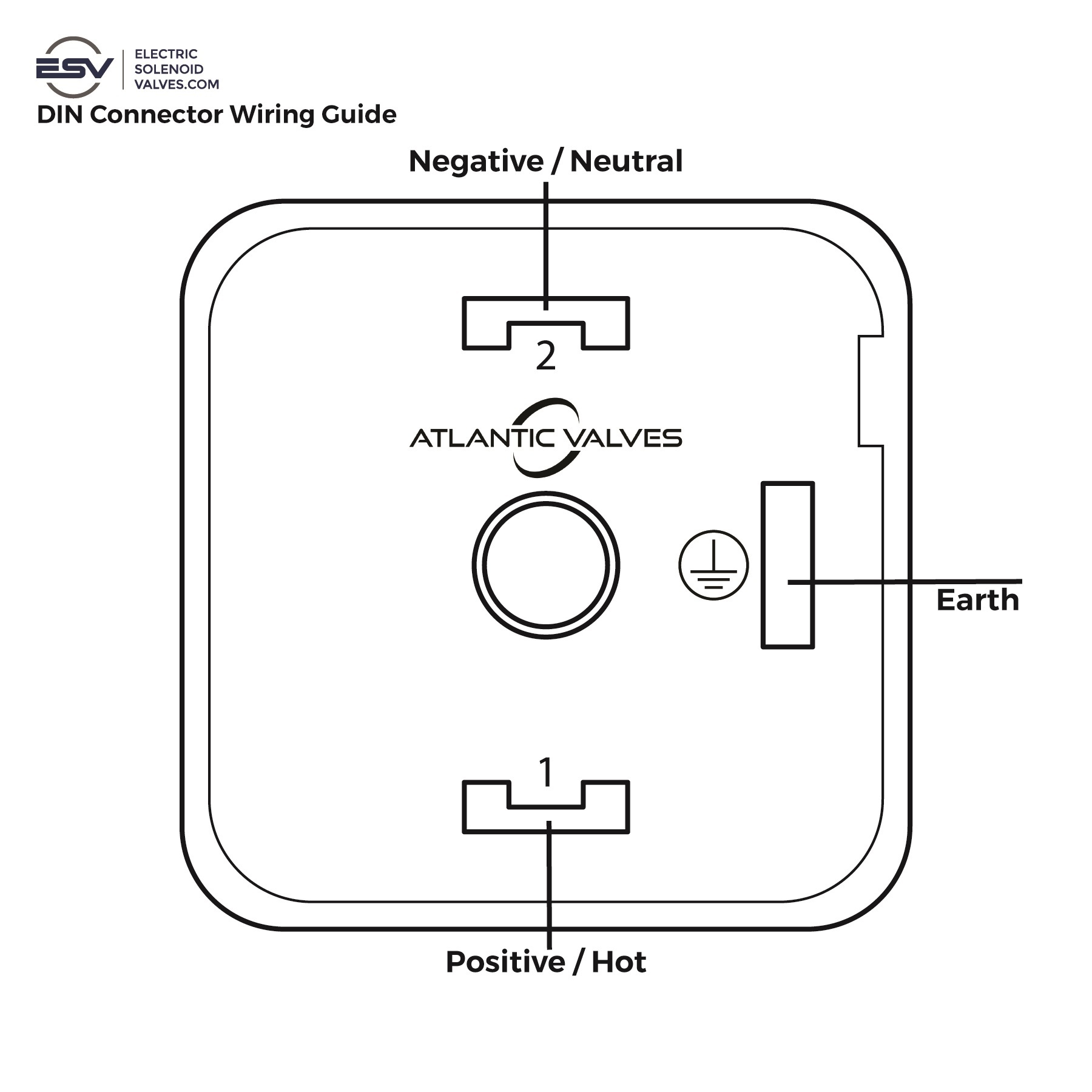
Polarity basics
- AC coils: non‑polarized — either lead can go to either terminal, plus ground.
- DC coils: polarity matters — connect + to terminal 1 and – to terminal 2 (most DIN plugs label 1/2 and earth).
- Ground/Earth terminal: used only with AC voltages. This terminal provides a safety path to ground in case of a fault, helping meet enclosure ratings like IP65/NEMA 4. DC coils do not require a ground connection, so you can leave the earth terminal unused in DC applications.
Always verify the insert card supplied with the connector.
See image below for a visual reference of the connection layout.
7) Duty cycle and heat: don’t cook the coil
“Duty cycle” = ON time / total cycle time. Heat rises with ON time, ambient temp, and fluid temp. Respect the duty cycle and enclosure rating to avoid overheating and premature coil failure.
Checklist:
- Match voltage and frequency (for AC).
- Provide adequate ventilation.
- If the coil gets too hot to touch, re-check duty cycle, voltage at the terminals, and ambient conditions.
8) Control methods—simple to advanced
Depending on your application, you can switch a solenoid valve with:
- Manual on/off switch (basic service)
- Timer (interval flushing, irrigation)
- Smart plug/smart relay (home automation)
- Microcontroller/PLC (sensor-based automation, interlocks)
ESV blogs cover basic control options and home/DIY automation patterns (smart plugs, sensor triggers), plus valve education content for wiring and function.
Part 3 — Flow Direction, Orientation & Start-Up
9) Respect the flow arrow and valve type
Most 2-way solenoids have an inlet (cavity port) and outlet (body/orifice port)—plumb accordingly. Normally Closed (NC) valves block flow until energized; Normally Open (NO) allow flow until power closes them. 3-way valves route between ports for actuation/vent tasks. Link your pick to how the circuit should behave on power loss.
10) Orientation and environment
For best results, mount coils upright (helps with longevity and drainage) and keep within the coil’s enclosure rating (e.g., IP65/NEMA 4 suitable for washdown/splash with proper installation; avoid continuous submersion unless rated): product pages and coil listings on ESV show enclosure class details.
11) First power-up: what “good” looks like
- Crack upstream isolation to slow-fill the line (reduces water hammer).
- Cycle the valve a few times while monitoring for leaks and proper actuation.
- Re-torque fittings only if needed after the system reaches steady state.
- If the valve chatters, runs hot, or fails to open, see the troubleshooting section and double-check ΔP requirements (some pilot-operated valves need a minimum differential; zero differential valves do not).
Part 4 — Troubleshooting & Reliability Boosters
Common symptoms and likely causes
- Valve leaks at threads → wrong thread standard/size, insufficient sealant, over-torque, or nicked seat; re-inspect thread ID and sealant technique.
- Valve hums, heats, or won’t actuate → wrong voltage, coil powered continuously beyond duty cycle, low ΔP (if pilot-operated), debris; verify specs and strainers.
- Intermittent operation → loose DIN terminals, moisture ingress beyond enclosure rating, undersized power supply, or wrong control method (e.g., rapid cycling).
If you’re deciding whether to repair or replace, ESV’s guidance hits the practical checkpoints—power off, depressurize, use proper sealing materials, and confirm upstream conditions before blaming the valve.
Part 5 — Quick Wiring Reference (DIN 43650A)
Always follow the included diagram with your specific connector/coil.
- AC coil: Line/neutral to the two screw terminals (non-polarized), earth to ground lug.
- DC coil: + to terminal 1, – to terminal 2 (or per insert). No ground connection is required for DC coils.
- Strain relief: Use the PG-style cable gland on the DIN plug; avoid side-loading the terminals.
ESV’s coil/valve pages call out “DIN 43650A”, enclosure class, and voltage options so you can confirm fit.
Part 6 — Smart Selection Notes Before You Buy
- Function: NC vs NO vs 3-way (how should the circuit behave on power loss?).
- Mechanism: Direct-acting/assisted-lift (good for zero differential), vs pilot-operated (needs minimum ΔP).
- Cv & orifice: Size to the required flow at your ΔP; then confirm port thread.
- Materials: Brass vs stainless, seals (e.g., Viton) per media and temperature. (See product pages for chemical compatibility notes.)
- Enclosure & environment: IP/NEMA rating, ambient, washdown exposure.
Step-by-Step: Putting It All Together
- Identify threads (standard + size) and gather the right fittings. Use the OD/TPI method and don’t mix standards.
- Install a Y-strainer upstream to protect small orifices/pilots. Choose mesh for your media.

- Seal the joints with 2–3 wraps PTFE tape (clockwise) or rated sealant. Support the body, avoid over-torque.
- Mount orientation per product guidance (coil up is best practice). Verify IP/NEMA class
- Wire the coil (check voltage, AC/DC, DIN terminals, and ground). Follow duty cycle guidance.
- Slow-pressurize and leak-test. Correct any bubbles, then cycle the valve and confirm function at operating ΔP. If low/zero ΔP, select a zero-diff model.
Final tips
- Plan your install around thread standard, flow (Cv), and control method first.
- Add filtration and proper sealant technique to prevent “mystery leaks.”
- Validate electrical (voltage/duty) and environmental (IP/NEMA) specs right on the product page to avoid early failures. (electricsolenoidvalves.com)
Need help matching ports and thread standard?
Use our NPT quick-ID guide and chart, then pick the valve that meets your Cv and pressure specs. Start here: Avoid Leaks: Match NPT Thread Size & Port for Solenoid Valves.
FAQs
How tight should I make NPT connections on a solenoid valve?
Tighten to manufacturer spec where available. As a rule of thumb, hand-tight plus 1–2 turns with a wrench is typical for small sizes—don’t over-torque. Always support the body with a backup wrench and leak-test at pressure.
Do I need thread sealant if the valve has NPT threads?
Yes—NPT seals by thread interference and typically requires PTFE tape (2–3 wraps, clockwise) or compatible pipe dope. Avoid over-taping.
My valve won’t open—could wiring be the issue?
Verify voltage and type (AC/DC) at the connector terminals, confirm correct DIN wiring, and check duty cycle/overheating. If the valve is pilot-operated, ensure you have the minimum ΔP; otherwise choose a zero-differential design
Can I mount the coil sideways?
Some valves allow various orientations, but coil-up is best practice for longevity and drainage. Also respect the IP/NEMA rating for your environment
Do ESV valves use DIN connectors?
Many do. Look for DIN 43650A noted on coil and product pages, along with IP65/NEMA 4 enclosure ratings and voltage options.